|
|
|
说明:双击或选中下面任意单词,将显示该词的音标、读音、翻译等;选中中文或多个词,将显示翻译。
|
|
|
1) cam profile

凸轮轮廓
1.
The equation of designing cam profile is brought forward and the functional relation between cam profile error and cam follower parameter error is deduced in this article.
提出了设计凸轮轮廓的方程式,推导出凸轮廓形误差与从动件各运动参数误差之间的函数关系式,指出了合理选用凸轮机构参数可适当提高从动件的运动精度,为今后合理确定凸轮廓形精度提供了新的方法和依据。
2.
The main point by the way is how to calculate the radius of eurvative of planar cam profile.
另外,在平面凸轮机构的综合中,一般也要验算凸轮轮廓曲线的曲率半径。
2) cam contour
凸轮轮廓
1.
Reverse seeking method on motion law of parallel indexing cam mechanism based on cam contour;
基于凸轮轮廓的平行分度凸轮机构运动规律的反求方法
2.
The machining quality of cam contour is a key fact to impact the operating property of a cam mechanism.
凸轮轮廓的加工质量是影响凸轮机构运行质量的关键因素。
3.
A general-utility cam contour CAD system is developed by taking advantage of C ~(++) Builder.
利用C++Bu ilder开发了具有通用性的凸轮轮廓CAD系统,该系统可灵活地调整凸轮设计精度,提供多种适应凸轮设计特点的从动件运动规律输入和设定方式,特别适用于凸轮从动件有复杂组合运动要求下的高精度凸轮轮廓设计。
3) Cam outline
凸轮轮廓
1.
In this paper it mainly states the equation on applying analytics to establish the cam outline curve and the cutting tool center orbit,thus we can work out the coordinate value and pressure angle from the every point of the cam outline line,we also can machine the cam outline on the numeral control machine tools and check the performance of the transmission force.
主要阐述用解析法建立凸轮轮廓曲线和刀具中心轨迹的数学方程式,准确地求出凸轮轮廓线上各点的坐标值和压力角,以实现在数控机床上加工凸轮轮廓并精确检验其传力性能。
2.
The cam outline date were calculated by C language programming and the calculation function warehouse of cam outline was constructed.
用C 语言编程计算凸轮轮廓数据并构造凸轮轮廓计算函数库。
3.
The proposed method provides an availability thought for 3D design of parameterized cam outline.
该方法通过改变设计参数,调整基准图形控制其特征形状,为凸轮轮廓参数化三维设计提供有效思路。
4) cam profile
凸轮轮廓线
1.
Research on cam profile of new style of naval gun s feed-on system;
新型舰炮供弹凸轮轮廓线设计的研究
5) cam profile
凸轮廓线
1.
A new method of CAD animation for drawing cam profile of engine;
发动机凸轮廓线生成的CAD动画新方法
2.
Optimal design of cam profile by means of non-uniform (B-spline) curve;
用非均匀B样条曲线优化设计凸轮廓线
3.
Through application of polar method to the equivalent four bar linkage of the cam mechanism, the principle of a new graphic method for determing the radius of curvature of planar cam profile is studied, the geometric and kinematic relationships are given.
通过瞬心法进行高副低代,得到了摆动从动件凸轮机构的等效四杆机构;在此基础上,论述了凸轮廓线曲率半径图解法的原理,给出了它们之间的几何运动关系。
6) cam profile
凸轮廓形
1.
On the basis of analyzing the non-impact seal cam profile, CNC methods of cam profile are given.
在对封闭凸轮廓形的分析基础上研究了凸轮廓形的数控加工方法。
补充资料:I-DEAS软件在平面凸轮槽加工中的应用
本文是用I-DEAS进行数控加工的一篇应用案例,作者通过本文较为生动地向广大读者诠释了如何用好软件才能解决好生产中遇到的难题。本文语言流畅、思路清晰、内容翔实,不仅对广大I-DEAS软件爱好者有较高的参考价值,而且对其他加工软件的编程人员也有很好的启迪作用。
I-DEAS 10 NX Series软件是美国UGS公司推出的一套包含计算机辅助设计、制造和工程分析(CAD/CAM/CAE)的集成软件系统,模块众多,功能强大。软件采用了主模型技术和当今CAD领域最先进的变量化造型系统,为企业新产品开发提供了完整的解决方案和强有力的技术支持。自从许昌烟草机械有限责任公司1998年购置I-DEAS软件以来,它就在烟机新产品开发的各个阶段得到了广泛的应用,极大地提高了产品质量,缩短了产品开发周期,创造了很好的经济效益。创成式加工(Generative Machining)是I-DEAS软件集成的加工模块,该模块提供了2.5~3轴铣削加工,4~5轴点位加工和车削加工,每种加工方式有多种加工策略供选择。创成式加工不仅可以直接加工由I-DEAS软件造型(Master modeler)模块设计的曲线、曲面和实体,而且可以对通过数据接口导入的其他CAD系统生成的零件进行NC编程。编程人员根据工件的特点,通过选择加工方式,制定加工策略,生成刀具路径,再通过软件提供的C-Post通用后置处理程序对生成的刀具路径编译,得到针对不同数控机床控制系统的加工程序,加工程序再通过DNC程序传输软件传输到数控机床进行加工,最终得到设计的零件。利用I-DEAS软件提供的强大功能,我们对卷烟机上使用的多种异型件进行了三维造型,设计了刀具路径,生成了加工程序,并在车间从瑞士进口的VCP1000高速铣床上试制成功。下面是我们利用I-DEAS软件解决平面凸轮槽加工难题的例子,写出来与大家交流。
一、问题的提出 我厂P70卷烟机有种平面凸轮槽零件,如图1所示。 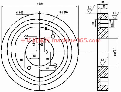
图1 P70卷烟机的平面凸轮槽零件 其中滚子中心轨迹由极坐标给出,图纸要求滚子在凸轮槽中运动光滑流畅,但是图纸中只给出了36个点的坐标,相当于每隔10°有一个坐标点,由于间隔过大,这些点不能准确地表达出凸轮滚子运动的规律,使加工无法进行。 二、问题的解决过程 1.失败的尝试 根据以往的经验,解决轮廓控制点间隔过大的问题需要在这36个坐标点之间插值进行细化,但是通过计算发现,如果保证两个插值点之间间距约0.5mm时,就要插入近400个点,计算量很大,而且无法确定点与点之间的插值方式,通过手工计算是很难完成插值的。为此,我们利用MasterCAM软件采集了近400个坐标点。以下是操作的简要过程。
说明:补充资料仅用于学习参考,请勿用于其它任何用途。
参考词条
|