1) functional component

功能部件
1.
An example of designing a functional component was given to show how to design the stamping die based on the assembly model.
基于现代设计方法理论和对冲模实际设计过程的认识 ,提出了一个基于模具功能部件的层次化装配模型 ,并介绍了基于该装配模型的冲模CAD系统工作模式和模具结构设计过程中不同层次上设计信息的处理方法 ,最后给出了一功能部件的设计实
2.
The analyzing method of ATR system, the functional components containing ATR system and ATR syslem consisting of several subsystems are described.
对ATR(自动目标识别)系统的分析方法和含有ATR系统之功能部件以及由多个子系统组成的ATR系统进行了阐述,其思路和方法可用于ATR系统的设计和评价。
2) Function componentslibrary
功能部件库
3) function name
功能部件名
4) Rolling Components
滚动功能部件
1.
Situation of the Rolling Components Industry of Our Country;
我国滚动功能部件产业现状分析
5) functional coupling components
功能耦合部件
1.
This article treats of the function and formations of functional coupling components and analyze in detail the working principld of functional coupling components by expounding respective assembly s working circuit diagram.
论述了功能耦合部件的功能、组成,及对部件各组合件工作电路的情况,详细分析了功能耦合部件的工作原理。
6) functional units design
功能部件设计
1.
An overview of the functional units design in Godson-2 processor is given and some details including architecture and physical design are described.
功能部件是处理器中进行指令运算的核心单元,它的算法及其实现直接影响到处理器的总体性能·介绍了龙芯2号处理器的功能部件,探讨了从算法到物理设计等不同层次的功能部件设计方法·龙芯2号功能部件分为两个定点ALU和两个浮点ALU实现,除实现完整的MIPS定、浮点指令集外,还实现了龙芯2号类MMX自定义多媒体指令集以及定点操作在浮点部件(FPU)中的数据通路复用·龙芯2号浮点部件遵照IEEE754和MIPS相关标准,浮点加法4拍完成,浮点乘法5拍完成,浮点除法4~17拍完成·物理设计支持0·18μm工艺下主频500MHz的标准单元实现,浮点单精度峰值性能达到2GFLOPS,双精度峰值性能达到1GFLOPS
补充资料:将UG里的一个装配部件输出成单个部件文件
法一:
- 关闭(turn off)FileàOptions->Load Options下"Partial Loading "选项
- 打开装配部件
- 选择File->Export->Part
- 在"Part Specification"下选择"new"
- 选择"Specify Part",指定输出部件文件名称及位置
- 将"Object Selection Scope"设定为"All Objects"
- 选择"Class Selection->Select All"高亮所有对象
- 按"OK"
该种方法特点:每一个部件的特征都会汇集在新部件的MNT里。可以方便编辑。
法二:
- 闭(turn off)File->Options->Load Options下"Partial Loading "选项
- 打开装配部件
- Application->Assembly
- Assemblies->Components->Create New,给出想要输出的部件文件名及路径。
- 如下图1,在ANT上双击新产生的部件文件,使其成为工作部件。
- Assemblies->WAVE Geometry Linker,将设置改为"Body",选择所有组件的体。
- 将"Create Non-associative"开关设为"On",见下图2
- 将产生的部件设成显示部件,仅保存刚产生的新部件,不保存旧的装配部件。
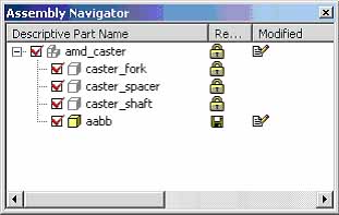 图1 | 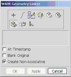 图2 |
该种方法特点:每一个部件在新部件的MNT里只会显示一个link的特征。没有相应特征可以编辑。
说明:补充资料仅用于学习参考,请勿用于其它任何用途。
参考词条