|
|
|
说明:双击或选中下面任意单词,将显示该词的音标、读音、翻译等;选中中文或多个词,将显示翻译。
|
|
|
1) Operation pathway

手术路径
2) Surgical approach
手术径路
1.
Evaluation of the surgical approaches of primary neurogenic tumors of the mediastinum;
外科治疗纵隔原发神经源性肿瘤的手术径路评价
2.
Objective To investigate the surgical approaches of the embedded supernumerary teeth in maxilla.
目的探讨上颌前部骨内埋伏多生牙的手术径路。
3.
Objective To discuss surgical approaches to carcinoma of gastric cardia.
目的探讨贲门癌合理手术径路的选择。
3) surgical approaches
手术径路
1.
Clinical study of surgical approaches to carcinoma of gastric cardia;
贲门癌手术径路的选择的临床研究
2.
The history,surgical approaches and related techniques are reviewed in this article so as to present a systemic view of lateral skull base surgery.
侧颅底外科近年来越来越受到耳神经学科医师的重视,该文对侧颅底外科的历史、手术径路以及相关技术作一概述,使临床上对其有一个系统的认识。
3.
Objective: To evaluate the methods of surgical approaches in treatment of carcinoma of the gastric cardia.
结论:贲门癌的3种手术径路中,选择胸腹联合切口较合理。
4) path planning of the brain
手术路径规划
5) surgical clinical pathway management system
手术临床路径管理系统
1.
Orienting the complexity of surgical processes,a surgical clinical pathway management system driven by workflow and the framework of the system were presented.
针对手术业务流程的复杂性,提出了基于工作流驱动的手术临床路径管理系统,并给出了其整体架构。
6) surgical approach
手术途径
1.
To explore the factors associated with the choice of surgical approach of hysterectomy and their roles in the decision-making,1238 patients with uterine leiomyomas received hysterectomy by four selected senior surgeons in Peking Union Medical College hospital between 2002 and 2006 was analyzed.
通过回顾分析(n=1238)和电话问卷调查(n=864),分析子宫切除术手术途径(开腹、腹腔镜、阴式)选择有关的因素,并探讨其在决策过程中的作用。
补充资料:Pro/ENGINEER中复杂几何路径的数组阵列
1 引言 Pro/ENGINEER是目前应用非常广泛的CAD/CAM软件,其功能非常强大。在Pro/ENGINEER中进行特征复制时, PATTERN(数组阵列)可以一次建立多个相同的特征,比COPY(复制)省时省力。 在实际应用中,阵列的几何路径有规则的(如直线形、圆形等),也有不规则的(如平行四边形、椭圆形等)。对于规则路径,其生成较简单,如圆形路径,选取一周向驱动尺寸,输入阵列的增量与个数即可。下面以在基座上钻孔为例,介绍不规则几何路径的数组阵列。 2 设计实例 首先,生成基座(如图1黑点表示孔的圆心位),其中心点位于Pro/ENGINEER中坐标系的原点,再钻出左上角的第一个孔(以基座的两条边为参考边,这两条边的交点为准原点)。然后进行数组阵列,产生其余的孔,依次选择“Pattern→General→Table”。 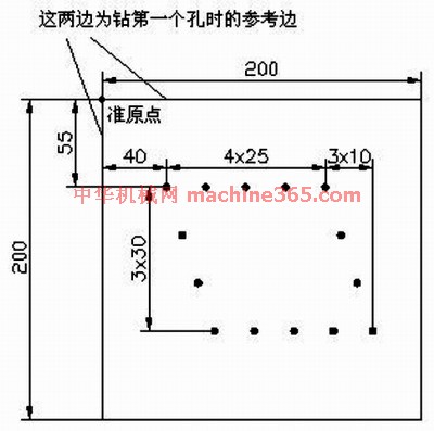
图1 黑点表示孔的圆心位 2.1 步骤一 选择图1中的尺寸“40,55”作为“表格驱动阵列的驱动尺寸”,然后选“Done”。 2.2 步骤二 选择“Add”,进行表的添加(输入一个表名如A),接着打开一个窗口,其中已有的文字均为注释语句,最后一行为: idx d4(40.0) d3(55.0) 其中,idx表示这一列填的是序号,从1开始;d后的数字以实际操作中产生的为准,括号内数值为步骤1中所选驱动尺寸的值,可以看出该值的显示顺序与尺寸的选择顺序是对应的。 2.3 步骤三 进行表的录入,依次填入:
1 65 55
2 90 55
3 115 55
4 140 55
5 50 85
6 60 115
7 70 145
8 95 145
9 120 145
10 145 145
11 170 145
12 150 85
13 160 115 其中1~4为上部右边的4个孔,5~7为左边3个孔,8~11为下部右边4个孔,12~13为右边剩余2个孔。 2.4 步骤四 首先点击“File→Save”,并且进行保存。然后点击“File→Exit”,退出程序。之后执行“Done”即可进行阵列,如图2所示。
说明:补充资料仅用于学习参考,请勿用于其它任何用途。
参考词条
|