1) involute cam

渐开线凸轮
1.
Research on Involute Cam Measuring Apparatus and Testing Technology about Involute Cam;
渐开线凸轮测量装置的搭建及测试技术的研究
2.
It is improved clamping device with involute cam,in order to carry out two-way clamping of the workpiece.
对渐开线凸轮夹紧机构进行了改进,使其能够对工件进行双向夹紧。
3.
Involute cam is an important attachment which produce involute profile in the copying gear grinder; the accuracy of which directly decide the profile accuracy of gear which is grinded.
渐开线凸轮是靠模式齿轮磨床生成渐开线齿形的重要附件,其精度直接决定着被磨齿轮的齿形精度。
2) involute gear
渐开线齿轮
1.
Confirmation of the measuring teeth number of involute gear common normal;
渐开线齿轮公法线跨测齿数的确定
2.
Accurate modeling of Involute gear machined by the principle of generation of curve;
基于曲线的生成原理实现渐开线齿轮的实体建模
3.
Exactitude Modeling of Involute Gear on Pro/E;
基于Pro/E的渐开线齿轮精确建模
3) involute contour
渐开线轮廓
1.
Copying turn the involute contour of automobile brake cam shaft;
仿形车削汽车制动凸轮轴的渐开线轮廓
4) Involute gears
渐开线齿轮
1.
This article introduced the three-dimensional molding design for involute gears based on SolidWorks,and put forward four methods of parameterized entity design of gears aiming to extend the application of SolidWorks in gear fields and to improve the efficiency of gear designing.
结合计算机辅助设计/制造的需要,基于SolidWorks软件平台,对渐开线齿轮的三维造型方法进行了探讨,提出了在SolidWorks环境下实现参数化齿轮实体设计的四种方法。
2.
This paper introduces the method of realization parameterized design of cylindrical involute gears based on unigraphics NX after inducing the general structure of cylindrical involute gears, and composers can get the new needed roughcast quickly by applying the models.
在Unigraphics环境下,在归纳了常见圆柱渐开线齿轮的结构基础上,利用其成形特征和表达式功能实现圆柱渐开线齿轮齿坯的参数化设计方法,可使设计人员能应用现有的模型进行更新设计,提高设计效率,并介绍了利用表达式、规律曲线和螺旋功能实现圆柱齿轮(直齿和斜齿)的精确建模。
3.
This paper introduces in detail some measuring and determining metho ds of the parameters of the straight and inclined involute gears that are more p ractical in the actual work.
详细介绍了实际工作中较实用的直齿渐开线齿轮、斜齿渐开线齿轮参数的测量与确定方法。
5) involutes gear
渐开线齿轮
1.
Numerical analysis for the elastohydrodynamic lubrication of involutes gear by a non-Newtonian medium;
渐开线齿轮传动非牛顿润滑介质的线弹流数值分析研究
2.
Through slicing and analyzing the model,contact stresses of involutes gear were measured and analyzed by using Hertz contact theory and finite element method.
根据相似原理将模型在载荷作用下进行应力冻结;通过模型切片及分析对渐开线齿轮接触应力进行测量,并采用赫兹接触理论和有限元方法分析渐开线齿轮的接触应力。
6) Involute worm wheel
渐开线蜗轮
1.
According to space relation of geometry,firstly we introduced forth-equivalent analytic geometrical equation of the sweep diameter and the pitches to three dimensional helix thread by giving an example of involute worm wheel.
以渐开线蜗轮为例,依据空间几何关系,给出了蜗轮三维螺旋扫掠路径与螺距的当量解析式,并利用MDT6。
补充资料:长度测量工具:渐开线测量仪
测量渐开线齿形的齿轮测量工具(见长度测量工具)。常见的有单盘式和万能式两种。
单盘渐开线测量仪 採用基圆盘直尺机构﹐以展成法(见齿轮测量)进行测量(图1 单盘式渐开线测量仪 )。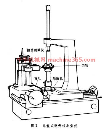 可测齿轮的最大直径一般不大於 600毫米。测量不同直径的齿轮时﹐需要配以相应的基圆盘。它适用於大批量生產中测量5~6级精度的齿轮﹐精度高的可测3~4级精度的齿轮。
万能渐开线测量仪 主要有3种。机械式万能渐开线和螺旋线测量仪(图2 机械式万能渐开线和螺旋线测量仪 )。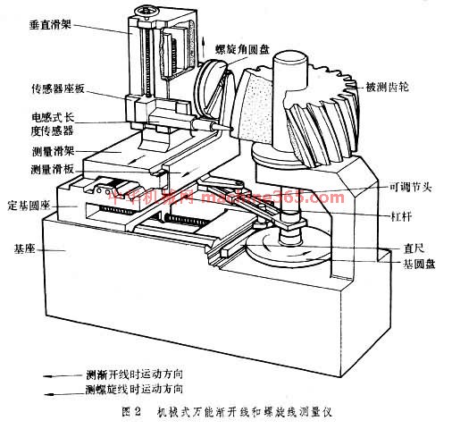 它採用槓桿式基圆可调机构﹐以展成法测量。测量滑架与测量滑板可以固定成一体﹐因此测量滑架移动时﹐通过可调节头﹑槓桿带动直尺使基圆盘和被测齿轮转动。可调节头轴心线和电感式长度传感器测头的刃口位於与被测齿轮基圆相切的同一平面内﹐所以刃口相对於被测齿轮的运动轨跡是渐开线﹐将这一运动轨跡与被测齿形比较﹐齿形误差即由长度传感器转换为电信号﹐并由记录器绘出误差曲线图。利用定基圆座可以按被测齿轮基圆半径确定可调节头轴心线与主轴轴心线间的距离﹐所以不需更换基圆盘即可测量不同直径的齿轮。图2 机械式万能渐开线和螺旋线测量仪 中的测量机构还可测量螺旋线误差。测量前﹐利用光学分度头(图 机械式万能渐开线和螺旋线测量仪 中未表示)调整螺旋角圆盘的直槽的倾斜角﹐使之等於基圆螺旋角﹐并使测量滑架与测量滑板鬆开。当垂直滑架移动时﹐通过螺旋角圆盘﹑测量滑板﹑可调节头﹑槓桿带动直尺使基圆盘和被测齿轮转动来测量螺旋线误差。机械式万能渐开线测量仪可测直径达2000毫米以上的齿轮﹐按被测齿轮直径不同﹐可测4~6级精度的齿轮。採用圆光栅﹑长光栅或激光干涉仪等作为坐标测量系统和电子计算机等作为控制﹑数据处理系统﹐以法线展开角坐标法测量的电子式万能渐开线测量仪。它可测3~5级精度的齿轮。利用直角坐标法测量的上置式万能渐开线测量仪﹐有机械式和电子式两种。前者由人工进行数据处理﹐效率极低﹐精度也不高﹔后者採用两个长光栅测量系统和电子计算机等分别作为直角坐标测量系统和控制﹑数据处理系统﹐测量效率和精度都较高﹐适宜於测量直径1000毫米以上﹑5级精度以上的大齿轮。
单盘渐开线测量仪 採用基圆盘直尺机构﹐以展成法(见齿轮测量)进行测量(图1 单盘式渐开线测量仪 )。
可测齿轮的最大直径一般不大於 600毫米。测量不同直径的齿轮时﹐需要配以相应的基圆盘。它适用於大批量生產中测量5~6级精度的齿轮﹐精度高的可测3~4级精度的齿轮。 万能渐开线测量仪 主要有3种。机械式万能渐开线和螺旋线测量仪(图2 机械式万能渐开线和螺旋线测量仪 )。
它採用槓桿式基圆可调机构﹐以展成法测量。测量滑架与测量滑板可以固定成一体﹐因此测量滑架移动时﹐通过可调节头﹑槓桿带动直尺使基圆盘和被测齿轮转动。可调节头轴心线和电感式长度传感器测头的刃口位於与被测齿轮基圆相切的同一平面内﹐所以刃口相对於被测齿轮的运动轨跡是渐开线﹐将这一运动轨跡与被测齿形比较﹐齿形误差即由长度传感器转换为电信号﹐并由记录器绘出误差曲线图。利用定基圆座可以按被测齿轮基圆半径确定可调节头轴心线与主轴轴心线间的距离﹐所以不需更换基圆盘即可测量不同直径的齿轮。图2 机械式万能渐开线和螺旋线测量仪 中的测量机构还可测量螺旋线误差。测量前﹐利用光学分度头(图 机械式万能渐开线和螺旋线测量仪 中未表示)调整螺旋角圆盘的直槽的倾斜角﹐使之等於基圆螺旋角﹐并使测量滑架与测量滑板鬆开。当垂直滑架移动时﹐通过螺旋角圆盘﹑测量滑板﹑可调节头﹑槓桿带动直尺使基圆盘和被测齿轮转动来测量螺旋线误差。机械式万能渐开线测量仪可测直径达2000毫米以上的齿轮﹐按被测齿轮直径不同﹐可测4~6级精度的齿轮。採用圆光栅﹑长光栅或激光干涉仪等作为坐标测量系统和电子计算机等作为控制﹑数据处理系统﹐以法线展开角坐标法测量的电子式万能渐开线测量仪。它可测3~5级精度的齿轮。利用直角坐标法测量的上置式万能渐开线测量仪﹐有机械式和电子式两种。前者由人工进行数据处理﹐效率极低﹐精度也不高﹔后者採用两个长光栅测量系统和电子计算机等分别作为直角坐标测量系统和控制﹑数据处理系统﹐测量效率和精度都较高﹐适宜於测量直径1000毫米以上﹑5级精度以上的大齿轮。
说明:补充资料仅用于学习参考,请勿用于其它任何用途。
参考词条