1) coherent structures


大涡结构
1.
Evolution of coherent structures in boundary layer with pressure gradients;


大涡结构在有压梯度边界层流中的演化机理
2.
The stability of 3-D plane boundary layer with local distributed roughness and the cause of coherent structures in shear flow are studied in detail.
本文利用x及y方向变间距的高精度紧致有限差分及z向Fourier谱展开相结合的方法,数值求解三维、非定常、不可压的Navier-Stokes方程,详细研究了壁面局部粗糙边界层的稳定性问题和近壁剪切流中大涡结构的成因机制。
2) large-scale vortical structure


大尺度涡结构
1.
The large-scale vortical structures produced by an impinging density jet in shallow crossflow were numerically investigated in detail using RNG turbulence model.
采用RNG湍流模型对浅水横流中异重冲击射流的大尺度涡结构进行了详细的数值研究。
3) large-scale vortical structures


大尺度旋涡结构
4) spiral large-scale vortices structure


螺旋大尺度涡结构
5) vortex structure


旋涡结构
1.
Investigation of vortex structure of the 2D backward facing step flow via PIV;


应用PIV进行二维后向台阶流流动特性的研究(1)二维后向台阶流的旋涡结构的研究
2.
The Investigation of Vortex Structure in Straight and Compound Lean Compressor Cascades Via PIV;
直弯扩压叶栅内旋涡结构PIV研究
3.
The flow filed of compressor cascades with three large camber angles at different incidences is measured by five-hole probe in details,and the influence of flow separation and vortex structure on the compressor bowed cascade aerodynamic performances was numerically studied.
在不同冲角下,采用五孔探针对三种大弯角压气机叶栅流场进行了详细测量,并利用数值模拟研究了流动分离和旋涡结构对弯叶栅气动性能影响。
6) vortex structure


涡结构
1.
The study of vortex structure of impinging jet calculated using the swirling strength method;
基于旋涡强度方法的冲击射流涡结构研究
2.
In this paper,vortex structures and flow patterns were studied by PIV(Particle Image Velocimetry) technique.
冲击射流广泛应用于短距、垂直起降飞行器(SVTOL)等航空航天领域,然而却伴随着流场与噪声等诸多方面的问题,笔者采用PIV(粒子图像测速)技术对超声速冲击射流的流场结构和涡结构进行了深入研究。
3.
The experiments were focused on the effect of leading-edge cross section on vortex structures for 50° sweep delta wings and on the maximum sweep angle at which the dual vortex structure exists.
通过水洞流动显示实验对低雷诺数非细长三角翼绕流流动结构进行了研究,特别是前缘剖面对50°三角翼绕流涡结构的影响及存在双涡结构时模型的最大后掠角。
补充资料:抽芯成型高差大的滑块多级锁紧结构
在压铸模设计中, 常常会遇到同一抽芯而各成型高度相差较大的零件, 如果采用斜拉杆或弯销抽芯, 习惯上采取的措施是增加滑块的高度,以满足滑块的退位空间,其结果是滑块的重量增加,模框的强度降低。
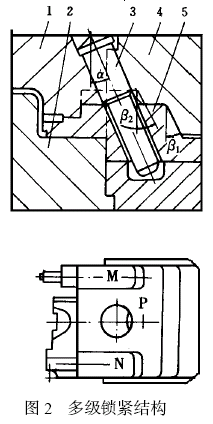
图1 是汽车油泵调速器前壳压铸件示意图, Ⅰ- Ⅰ分型面需用抽芯才能完成脱模,其最低抽芯高度Hmin 为17mm, 最大抽芯高度Hmax为45mm, 为了保证滑块有足够的退位空间而不发生自锁, 滑块的高度必须大于或等于45mm。为避免抽芯距离过大造成滑块体积增加, 在设计中采用了局部增高多级锁紧结构,如图2 所示。P 是高于17mm低于45mm的面,N是高于45mm的面,M面是与N面同高且保证N 面受力平衡的辅助结构。α为抽芯角,β1 、β2 为锁紧角,β1 、β2 不仅具有锁紧作用,而且在开模抽芯时还具有让位的作用,所以β1 、β2 必须大于α, 而且β2 应大于β1 , 否则开模时, 滑块会出现自锁。锁紧角β2 也可以等于β1 , 但由于制造时有误差, 如果误差大, 则β1和β2 形成的锁紧面会出现干涉。在压铸件调速器前壳模具设计中, α取23°, β1 取26°, β2取30°,实现了安全生产。


总之, 对于那些抽芯高度相差大的滑块,采用多级锁紧结构,对减小滑块的重量、延长模具寿命,节约模具材料具有重要的作用。
说明:补充资料仅用于学习参考,请勿用于其它任何用途。
参考词条