|
|
|
说明:双击或选中下面任意单词,将显示该词的音标、读音、翻译等;选中中文或多个词,将显示翻译。
|
|
|
1) layered shells

复合圆柱壳
2) Composite cylindrical shell
复合材料圆柱壳
1.
Following Loves shell theory, the governing equations of the composite cylindrical shell associated with asymmetric deformation perturbance were obtained.
应用 L ove的壳体理论得到了非轴对称变形的复合材料圆柱壳的控制方程。
2.
A new systematic methodology for solving composite cylindrical shell structure, new type complex series methodology, is developed which is used to produce the general analytical solutions for the problem of bending, buckling,vibration of composite cylindrical shell structure.
本文考虑剪切变形的复合材料圆柱壳结构解析求解新体系一新型复级数体系,以此建立了考虑剪切变形的复合材料圆柱壳结构线性弯曲、振动、稳定问题一般解析解。
3.
Based on the correlation between the structure stability and its vibration behavior, the measured vibration frequency is regarded as the monitor parameter of buckling limit point of composite cylindrical shells.
本文根据结构振动与稳定性的相关性,以振动频率测试值作为监控参数进行了复合材料圆柱壳的失稳状态监测。
3) laminated composite cylindrical shells
复合材料层合圆柱壳
1.
Finite element analysis for laminated composite cylindrical shells;
复合材料层合圆柱壳的有限元分析
4) thick laminated cylindrical shells
复合材料层合厚圆柱壳
5) composite thin-cylindrical panel
复合材料圆柱壳壁板
1.
The vibration characteristics of a composite thin-cylindrical panel embedded with shape memory alloy wires under thermal condition are investigated.
采用有限元软件ABAQUS实现了埋入形状记忆合金(SMA)丝的复合材料圆柱壳壁板结构热振动特性分析。
6) thin cylindrical shell composite
薄圆柱壳复合材料
补充资料:壳体零件的复合挤压
[摘要]介绍了壳体事件的挤压复合成形工艺,分析了挤压加工与机加工两种加工方法的材料利用率,设计计算了壳体零件的挤压件田,并设计了模具结构。
[关键词]:壳体零件;复合挤压模;材料利用率
军工产品壳体零件如图1所示,该零件外径的尺寸精度为O.12mm,表面粗糙度要求较高,零件材料为高强度硬铝2A12。其成份为:铜3.9%-4.8%;镁1.2%-1.6%;锰O.3%-O.9%;其余为铝。这种材料可以进行热处理强化,有较高的强度和耐热性。
该零件如果用机加工制造.不仅需要添置较多的机加工设备,而且加工时间长,浪费材料。采用挤压加工工艺不仅流程简单,生产操作方便,而且金属的力学性能良好。 可以把该零件分为上、中、下3段圆环,用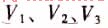 ,分别表示上、中、下3段圆环的体积。该零件总的体积V为: ,分别表示上、中、下3段圆环的体积。该零件总的体积V为: 
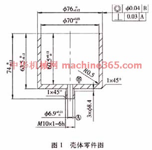
如果该零件机加工,假定单边加工余量为1.5mm,应该采用∮79×77mm的坯料,其体积为377429mm3。如果采用挤压加工,需要坯料有良好的流动性,所以在挤压前需要对坯料进行软化退火处理。其具体的退火热处理过程为:加热至410℃,保温6h,炉冷到150℃然后再空冷,这样软化处理后的硬度为53HB。退火热处理后的坯料,投有时效硬化现象,对于以后的冷挤压工序有利。 该壳体零件呈上杯下杆型,可进行复合挤压成型。挤压件底部厚度可以达到设计要求,不再需要机加工,大大节省了材料和工作量。零件的杆部为M10mm螺纹,无法挤压成型,可以后续机加工。 另外,在设计挤压件时要注意增加MlOmm杆部直径。因为如杆部太细,即使挤压件挤压成功,挤压件被顶料杆顶出时,也会在顶料力的作用下严重变形,使产品不合格。将杆部适当放粗至∮16mm。杆部的内孔直径为∮6.9mm,不宜挤压成型。因为如凸模工作部份顶墙尺寸太小,在挤压过程中容易断裂。 由于金属的各向异性,杯口部分不一定平整,所以要在杯的高度留加工余量1.5mm,以保证零件的外形尺寸。 挤压件如图2所示。 
说明:补充资料仅用于学习参考,请勿用于其它任何用途。
参考词条
|