|
|
|
说明:双击或选中下面任意单词,将显示该词的音标、读音、翻译等;选中中文或多个词,将显示翻译。
|
|
|
您的位置: 首页 -> 词典 -> 扩展最短路径算法
1) Extend short path algorithm

扩展最短路径算法
2) shortest path algorithm
最短路径算法
1.
Research on Shortest Path Algorithm Based on Graph in Dynamic Navigation System;
基于图论的动态导航系统最短路径算法研究
2.
This method gets the connection relationship by using the breadth first search algorithm,meanwhile puts forward the shortest path algorithm,which passes each vertex in the completed.
首先采用广度优先搜索算法得到原理图中元件端子的连接关系,同时提出了完全无向图中经过每个顶点一次且仅一次的最短路径算法和改进的Prim最小生成树算法,利用这两个算法可自动生成屏内安装接线图和端子接线图。
3.
Based on the thorough analysis of the network communication of the Network-on-Chip(NoC) and study of the shortest path algorithms, a directed Ford-Fulkerson algorithm is proposed in this paper.
文章通过对NoC网络通讯的分析,以及对现有最短路径算法的研究,提出了一种定向Ford-Fulker-son算法,实现了NoC路径分配;在完成处理单元映射后,根据NoC网络的通讯状况,按照通讯任务的时间顺序分配传输路径,使得任意处理单元间的通讯时间最短,且整个系统的执行时间最优。
3) the shortest path algorithm
最短路径算法
1.
Research of the the shortest path algorithm of urbanized public traffic networks;
城市公交网络的最短路径算法研究
4) the shortest path and algorithm
最短路径及算法
5) shortest-path algorithm
最短路径算法
1.
Proposed shortest-path algorithm using slightly modified Pulse-Coupled Neural Network.
提出了一种基于脉冲耦合神经网络(Pulse- Coupled Neural Network,PCNN)的最短路径算法。
2.
The algorithm maintains network connectivity only based on locally collected information and adjusts the topology structure according to the shortest-path algorithm by calculating the link weight.
该算法利用网络中所有节点的局部信息保持网络的连通性,同时,利用最短路径算法计算链接权值的大小来进行拓扑结构的调整。
6) floyd-shortest-path
Floyd最短路径算法
补充资料:Pro/ENGINEER中复杂几何路径的数组阵列
1 引言 Pro/ENGINEER是目前应用非常广泛的CAD/CAM软件,其功能非常强大。在Pro/ENGINEER中进行特征复制时, PATTERN(数组阵列)可以一次建立多个相同的特征,比COPY(复制)省时省力。 在实际应用中,阵列的几何路径有规则的(如直线形、圆形等),也有不规则的(如平行四边形、椭圆形等)。对于规则路径,其生成较简单,如圆形路径,选取一周向驱动尺寸,输入阵列的增量与个数即可。下面以在基座上钻孔为例,介绍不规则几何路径的数组阵列。 2 设计实例 首先,生成基座(如图1黑点表示孔的圆心位),其中心点位于Pro/ENGINEER中坐标系的原点,再钻出左上角的第一个孔(以基座的两条边为参考边,这两条边的交点为准原点)。然后进行数组阵列,产生其余的孔,依次选择“Pattern→General→Table”。 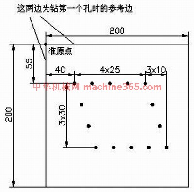
图1 黑点表示孔的圆心位 2.1 步骤一 选择图1中的尺寸“40,55”作为“表格驱动阵列的驱动尺寸”,然后选“Done”。 2.2 步骤二 选择“Add”,进行表的添加(输入一个表名如A),接着打开一个窗口,其中已有的文字均为注释语句,最后一行为: idx d4(40.0) d3(55.0) 其中,idx表示这一列填的是序号,从1开始;d后的数字以实际操作中产生的为准,括号内数值为步骤1中所选驱动尺寸的值,可以看出该值的显示顺序与尺寸的选择顺序是对应的。 2.3 步骤三 进行表的录入,依次填入:
1 65 55
2 90 55
3 115 55
4 140 55
5 50 85
6 60 115
7 70 145
8 95 145
9 120 145
10 145 145
11 170 145
12 150 85
13 160 115 其中1~4为上部右边的4个孔,5~7为左边3个孔,8~11为下部右边4个孔,12~13为右边剩余2个孔。 2.4 步骤四 首先点击“File→Save”,并且进行保存。然后点击“File→Exit”,退出程序。之后执行“Done”即可进行阵列,如图2所示。
说明:补充资料仅用于学习参考,请勿用于其它任何用途。
参考词条
|