|
|
1) system tool

系统工具
1.
Integrating with the applied technology of GIS,the article explains the system tools,function module of developing CATV-GIS in detail,and the application in planning and building,resource management,run- ning & maintenance and safe transmission of the network for CATV-GIS.
结合GIS应用技术,详细阐述了开发CATV-GIS的系统工具、功能模块及CATV-GIS在网络规划建设、资源管理、运行维护和安全传输中的应用。
2) Tool System
工具系统
1.
Comparative Analysis Between the Germanic DIN Standard and ISO Standard of HSK Tool System;
HSK工具系统DIN标准与ISO标准比较分析
2.
The tool system for HSC is studied in detail, the shortcoming of conventional 7∶24 cone tool system is analyzed, the tool-holder and its interface technology with spindle which having been used and being studied are introduced, and finally the development trends of tool system are put forward.
对高速加工的工具系统进行了详细研究,分析了传统7∶24锥度工具系统存在的缺陷,对已投入应用和正在研究的刀柄及其联接技术作了介绍,概括了其发展趋势。
3.
The main factors influencing the accuracy of dynamic balance of tool system for high speed machining are analyzed.
分析了影响高速加工工具系统动平衡精度的主要因素 ,讨论了高速加工工具系统动平衡精度等级的确定原则 ,明确给出了HSK工具系统动平衡精度的有效范围 ,这些研究工作有助于工具系统的正确制造和合理使
3) tooling system
工具系统
1.
Studying on balancing processing of tooling system;
工具系统平衡工艺的研究
2.
The shortcoming of conventional 7:24 cone tooling system is analyzed , many new tooling systems which have been used and being studied at home and b road are introduced, and the main problems and solutions in study on the tooling system is put forward.
在分析传统BT工具系统存在的缺陷基础上,介绍了国内外高速加工新型工具系统的研究现状,提出了研究中存在的主要问题及对策,展望了高速加工工具系统的发展趋势。
4) HSK tooling system
HSK工具系统
1.
And a proper clamping force is found to be essential to assure the axial and radial orientation precisions of the HSK tooling system in high speed machining (HSM).
运用弹性力学和材料力学理论,通过理论分析和试验方法研究了HSK工具系统静态和动态的定位精度,给出了夹紧力和刀柄锥度的关系,并进一步指出合适的夹紧力是保证HSK工具系统在高速加工时轴向和径向定位精度的必要条件。
2.
According to the structure of the hohl schaft kegel(HSK) tooling system and its working principle, a mechanical model of the HSK tooling system is established.
根据HSK工具系统的结构和工作机理建立了HSK工具系统的力学模型,分析了影响工具系统刚度的主要因素和载荷与加工质量之间的关系,揭示出HSK工具系统刚度变化的基本规律,理论分析结果与实验结果吻合。
3.
Based on the high speed machining,the failure form,failure reason and style in different location of the HSK tooling system are analyzed systematically from the safety of both the human and equipment.
以高速加工为背景,从人和物两方面的安全出发,对高速加工HSK工具系统不同部位的失效形式、失效原因和失效类型进行了系统分析。
5) HSK tool system
HSK工具系统
1.
Experimental researches were done with the positioning precision of HSK tool systems.
对HSK工具系统的定位精度进行了实验研究,揭示出夹紧力和刀柄锥面与主轴孔锥面之间阻力的相互依存关系及其对定位精度的影响。
2.
Using integrated software of CAD/CAE,the accurate digital 3D model of HSK tool system is established,the natural frequency and model shape is calculated by FEM on the basic of establishing reasonable boundary condition and plotting mesh.
利用CAD/CAE集成软件,首先建立了精确的HSK工具系统数字化三维模型,在建立合理的边界条件和划分网格的基础上,对其进行固有频率和振型的有限元计算,为HSK工具系统的动力特性设计和模态实验分析提供重要的依据。
3.
With the use of CAD/CAE integrated software,this paper establishes 3D digital model of HSK tool system for it s various structures and various diameters and lengths of cutter arbor.
利用CAD/CAE集成软件建立了不同结构、不同刀杆直径和长度的HSK工具系统数字化三维模型,在建立合理的边界条件和划分网格的基础上,分别对它们的临界转速进行了数值计算,经过比较和分析,得到的相关结论可以为正确设计HSK工具系统提供指导。
6) CAPP tool system
CAPP工具系统
1.
The research contents and characteristics of products-oriented CAPP system were discussed,the object-oriented information model was established,and the architecture framework of CAPP tool system was built.
论述了面向产品的CAPP系统的基本内容及其特点,建立了面向对象的CAPP系统的信息模型,构建了CAPP工具系统的体系结构框架。
2.
In this dissertation, the theory, methods and key technologies of CAPP tool system based on multi-technology fusion for products are studied systematically.
本文深入研究了面向产品基于多技术融合的CAPP工具系统实现的原理、方法及关键技术,开发了基于多技术融合的CAPP工具系统,并应用于液压缸产品的工艺设计系统中。
补充资料:长度测量工具:工具显微镜
以测量显微镜瞄準﹑能在﹑两个坐标内进行测量的通用光学长度测量工具(图1 万能工具显微镜 )。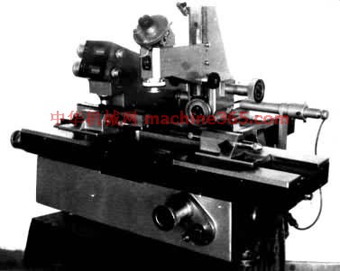 测量显微镜又称主显微镜。它的分划板上有供瞄準用的米字形﹑螺纹轮廓形和其他形状的标线。工具显微镜是20世纪20年代初期发展起来的﹐初期用於螺纹测量等﹐20年代后期出现万能工具显微镜。70年代以后﹐应用光栅测长技术后出现数字显示工具显微镜。80年代中期出现应用电子计算机技术处理测得数据的工具显微镜。 测量显微镜又称主显微镜。它的分划板上有供瞄準用的米字形﹑螺纹轮廓形和其他形状的标线。工具显微镜是20世纪20年代初期发展起来的﹐初期用於螺纹测量等﹐20年代后期出现万能工具显微镜。70年代以后﹐应用光栅测长技术后出现数字显示工具显微镜。80年代中期出现应用电子计算机技术处理测得数据的工具显微镜。
分类和结构 工具显微镜分小型﹑大型和万能 3种类型﹐其常见的测量范围分别为50×25毫米﹐150×75毫米和200×100毫米。它们都具有能沿立柱上下移动的测量显微镜和坐标工作台。测量显微镜的总放大倍数一般为 10倍﹑20倍﹑50倍和100倍。小型和大型的坐标工作台能作纵向和横向移动﹐一般採用螺纹副读数鼓轮﹑读数显微镜或投影屏读数﹐也有採用数字显示的﹐分度值一般为10微米﹑5微米或1微米。万能工具显微镜的工作台仅作纵向移动﹐横向移动由装有立柱和测量显微镜的横向滑架完成﹐一般採用读数显微镜﹑投影屏读数或数字显示﹐分度值为1微米。工具显微镜的附件很多﹐有各种目镜﹐例如螺纹轮廓目镜﹑双像目镜﹑圆弧轮廓目镜等﹐还有测量刀﹑测量孔径用的光学定位器和将被测件投影放大后测量的投影器。此外﹐万能工具显微镜还可带有光学分度台和光学分度头等。
用途和测量方法 工具显微镜主要用於测量螺纹的几何参数﹑金属切削刀具的角度﹑样板和模具的外形尺寸等﹐也常用於测量小型工件的孔径和孔距﹑圆锥体的锥度和凸轮的轮廓尺寸等。工具显微镜的基本测量方法有影像法和轴切法。影像法﹕利用测量显微镜中分划板上的标线瞄準被测长度一边后﹐从相应的读数装置中读数﹐然后移动工作台(或横向滑架)﹐以同一标线瞄準被测长度的另一边﹐再作第二次读数。两次读数值之差即被测长度的量值。图2 用影象法测量样板尺寸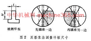 为利用影像法测量样板的L 尺寸。轴切法﹕测量过程与影像法相同﹐但瞄準方法不同。测量时分划板上的标线不直接瞄準被测长度的两边﹐而瞄準与被测长度相切的测量刀上宽度为3微米的刻线﹐以此来提高瞄準精度(见螺纹测量)。 为利用影像法测量样板的L 尺寸。轴切法﹕测量过程与影像法相同﹐但瞄準方法不同。测量时分划板上的标线不直接瞄準被测长度的两边﹐而瞄準与被测长度相切的测量刀上宽度为3微米的刻线﹐以此来提高瞄準精度(见螺纹测量)。
说明:补充资料仅用于学习参考,请勿用于其它任何用途。
参考词条
|