1) Large-sized 3D surface measurement

大尺寸三维形貌测量
2) 3-D shape measurement
三维形貌测量
1.
A novel method for 3-D shape measurement is presented.
提出一种新的投影栅三维形貌测量的实现方法。
2.
Errors that are caused by Laser speckle, mixing frequency, deformation of cosine fringes and perspective projection are corrected in the 3-D shape measurement system using structured light.
同时,通过将计算机算法、程序和控制硬件加以整合,最终建立了采用面结构光照明的、基于三维拼接技术的、实用、快速、精确的360°三维形貌测量系统。
3) 3D shape measurement
三维形貌测量
1.
Target location is a crucial part of 3D shape measurement, because it determines the measuring precision of system to a great extent.
标志点定位是三维形貌测量的关键技术之一,其精度在很大程度上决定着系统的测量精度。
4) three-dimensional shape measurement
三维形貌测量
1.
In order to overcome the disadvantage of Gabor transform analyzing nonstationary signals, dilating Gabor transform is applied to analyze the optical fringes of three-dimensional shape measurement.
为了克服窗口傅里叶变换在分析非平稳信号所存在的缺陷 ,基于窗口傅里叶变换技术提出了伸缩傅里叶变换法并应用于三维形貌测量中。
2.
Three-dimensional shape measurement of object surface is now widely applied in different areas, such as reverse engineering, computer vision, online product inspection and medical diagnosis.
物体表面三维形貌测量在逆向工程、机器视觉、在线产品检测以及医疗诊断等领域的应用日益广泛。
5) 3-D profilometry measurement
三维形貌测量
1.
Theory analyses of moiré stripe in 3-D profilometry measurement;
三维形貌测量的莫尔条纹的理论分析
6) three dimensional shape measurement
三维形貌测量
1.
Phase-shifting measurement is commonly applied in three dimensional shape measurement,in which it is important to obtain a precise phase-shift.
计算机编程产生脉冲输出给IPC373工控板控制步进电机运转,再通过机械装置实现投影光栅的微操动,从而现实三维形貌测量的相移。
2.
A new three dimensional shape measurement system is presented in this article, which is the digital three dimensional shape measurement system with DLP(digital light projector).
三维形貌测量是目前信息光学界的前沿领域之一,一直以来都受到人们的广泛关注。
补充资料:工程图标准尺寸及坐标尺寸
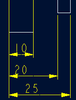
标准标注类型,是我们常用的标注类型。而坐标标注是便于数控加工采用的另一中标注形式。PRO/E可以将两种标注方式进行转换。
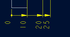
· 3.2 标准标注到坐标标注的转换
注意: 转化为坐标标注的尺寸必须是线性标注的,下列尺寸不能转化为坐标标注:
- 被显示成线性尺寸的直径
- 中心线尺寸
- 选择MODIFY DRAW > Dim Params > Dim Type > Ordinate Dim > Create Base.
- 选择作为参考基准线的尺寸
- 选择基准的引出线,该点为0点
- 选择 MOD DIM TYPE > Lin to Ord .
- 选择线性尺寸:注意:必须选择具有相同基准的尺寸
 ========>>>>
1. 选择 DIM PARAMS > Diam Dim Type .
2.点击Ord to Lin 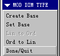
3.选择尺寸即可
说明:补充资料仅用于学习参考,请勿用于其它任何用途。
参考词条