1) complex torque coefficient-test signal method

复转矩系数-测试信号法
2) complex torque coefficient method
复转矩系数法
1.
The two methods,the complex torque coefficient method realized by time-domain simulation method—the test signal method and the time-domain simulation method,which are used to analyze the subsynchronous resonance(SSR) for multi-machine systems with the help of the well-known electromagnetic transient simulation software PSCAD/EMTDC are recommended.
介绍了采用国际著名电磁暂态仿真软件PSCAD/EMTDC对多机系统次同步谐振进行分析时主要用到的两种方法:基于时域仿真实现的复转矩系数法—测试信号法,时域仿真法。
2.
The thoeretical basis and the utilization conditions of thecomplex torque coefficient method are established.
应用复变函数理论导出了复转矩系数与特征值之间的关系,从而建立了复转矩系数法的理论基础和使用条件。
3.
The model is validated on the EPRI HVDC system by eigenvalue analysis and complex torque coefficient method.
基于EPRI直流系统,分别采用特征值分析法和复转矩系数法将HVDC换流器的准稳态模型、采样—数据模型与PSCAD时域仿真进行了对比验证。
3) complex torque coefficient approach
复转矩系数法
1.
In this paper, the applicability of the complex torque coefficient approach, which is widely used in the analysis of subsynchronous oscillation (SSO)of power systems, is analyzed.
针对广泛应用于电力系统次同步振荡分析的复转矩系数法 ,对其成立的基本前提进行了分析 ,在此基础上研究了其适用范围。
2.
Aiming at this problem,the paper analyzes the influence of SSR under different generator output and different degree of series compensation through adopting complex torque coefficient approach based on time domain simulation.
针对输电网中串联电容补偿引发的次同步谐振,文章采用基于时域仿真实现的复转矩系数法分析了不同发电机出力以及不同串补度对系统次同步谐振的影响。
4) complex torque approach
复转矩系数法
1.
The complex torque approach realized by frequency scanning and time domain simulation was adopted to study the SSR dangerous of IEEE SSR first benchmark model, and time domain simulation was used to prove the correctness of this method.
以IEEE次同步谐振第1标准模型为研究对象,采用扫频和时域仿真相结合的复转矩系数法,从系统阻尼特性的角度分析了系统发生SSR的危险性,并用时域仿真法验证了该方法的正确性。
5) complex torque coefficient
复转矩系数
1.
The concept of complex torque coefficient was extended to the design of HVDC supplementary controller.
将复转矩系数法的概念进行了推广,并应用到直流附加阻尼控制器的设计中。
6) test signal method
测试信号法
1.
Firstly,the electrical damping versus frequency in different series compensation degrees and different operating conditions is calculated using the complex torque coefficient method realized by time domain simulation,namely the test signal method.
首先采用基于时域仿真实现的复转矩系数法-测试信号法计算了不同串补度和运行工况下发电机组的电气阻尼频率特性;然后据此计算出使次同步谐振不发散所需的最小发电机机械阻尼,并与已知的发电机机械阻尼进行了比较,判断出不同串补度和运行工况下神木电厂一期串补送出方案的次同步谐振稳定性;最后采用PSCAD/EMTDC,基于发电机组轴系的多刚体模型进行了时域仿真,验证了已得到的结果。
2.
By using test signal method,the sub-synchronous electrical damping characteristics of a generator and the impacts of the designed SEDC on the generator s electrical damping are analyzed.
采用测试信号法,通过计算发电机组的次同步电气阻尼特性,分析所设计的SEDC对发电机组次同步振荡的抑制效果。
3.
The effects of the power system stabilizer(PSS)on subsynchronous resonance(SSR) damping are studied in this paper based on the IEEE SSR first benchmark model and the IEEE ST1A type excitation system by means of complex torque coefficient approach,namely the test signal method,realized by time domain simulation.
采用时域仿真实现的复转矩系数法——测试信号法,基于IEEE次同步谐振第一标准测试系统及IEEE ST1A型励磁系统,研究了电力系统稳定器(PSS)对次同步谐振的抑制效果。
补充资料:板料冲压性能及测试--厚向异性系数
厚向异性系数r(也叫塑性应变比r,简称r值)是评定板料压缩类成形性能的一个重要参数。r值是板料试件单向拉伸试验中宽度应变εb与厚度应变εt之比,即
r=εb/εt
板料r值的大小,反映板平面方向与厚度方向应变能力的差异。r=1时,为各向同性;r≠1时,为各向异性。当r>1,说明板平面方向较厚度方向更容易变形,或者说板料不易变薄。r值与板料中晶粒的择优取向有关,本质上是属于板料各向异性的一个量度。
r值与冲压成形性能有密切的关系,尤其是与拉深成形性能直接相关。板料的r值大,拉深成形时,有利于凸缘的切向收缩变形和提高拉深件底部的承载能力。图1示出拉深时的应力状态,对照各向异性板料的屈服椭圆(图2)知;拉深件凸缘的应力状态类似于屈服椭圆第二象限区的情况,而底部的应力状态则类似于第一象限区的情况。r值增加,会同时使底部的强度增加和凸缘的变形抗力减小,这对拉深是非常有利的。大型覆盖件成形,基本上是一咱拉深与胀形相结合的复合成形,当拉深变形的成分占主导地位时,板材r值大,成形性能好。
板平面中最主要的三个方向是与轧制方向呈0°、45°和90°,相应地用r0、r45和r90表示。由于不同方向上测得的数值是变化的(图3),板料的厚向异性系数常用平均值r表示。
板平面内各向异性的差别用△r表示。
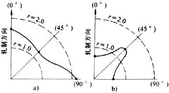
图1 拉深时的应力状态
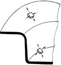
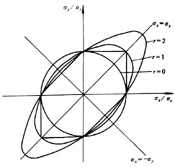
图3 r值在板平面内的变化
说明:补充资料仅用于学习参考,请勿用于其它任何用途。
参考词条