|
|
|
说明:双击或选中下面任意单词,将显示该词的音标、读音、翻译等;选中中文或多个词,将显示翻译。
|
|
|
1) sliding path

滑移路径
1.
Regard to the complex spatial structure of united dam-power house built in the river bed, 3D non-linear finite element method(FEM) and genetic algorithm are used to study such research works as stress and strain analysis、 stability of dam foundation 、 failure mechanism and determination of sliding pathes of house-dam block of TuKa Hydro-project.
4、根据有限元法计算出的应力场定义深层任意滑裂面抗滑稳定安全系数,引入自适应遗传算法对重力坝的深层滑移路径进行搜索计算,从而确定最危险的滑移路径并得到相应定量的安全系数。
2) dangerous slide path
危险滑移路径
1.
The algorithm of searching dangerous slide path of the rock slope without obvious controlling discontinuities is improved,and the method of adopting dynamic planning method which is based on the criterion of minimum slide-resisted reserve density to confirm dangerous slide path is proposed.
对无明显滑面岩质边坡危险滑移路径的搜索算法进行了改进研究,提出以总抗滑储备密度最小为判据的动态规划方法来确定边坡的危险滑移路径及其安全系数大小的方法,并通过算例得到了验证。
3) expected slide path
期望滑移路径
4) path smoothing
路径平滑
5) smoothing path
光滑路径
6) migration pathway
运移路径
1.
Application of NMR imaging technique to quantitative observation and analysis on hydrocarbon migration pathway;
核磁共振成像技术在油气运移路径观察与分析中的应用
2.
On the basis of raster data structure of GIS, directed by oil and gas reservoir formation theory, and using the GIS modeling method of surface water flow direction analysis for reference, this paper designs a special GIS-based algorithm to simulate oil and gas migration pathways, and proposes a GIS-based oil and gas migration pathway modeling flow.
以GIS的栅格数据结构为基础 ,按照油气运移的机理 ,借鉴地表水流向分析的GIS建模方法 ,构建了在GIS支持下开展油气运移路径模拟的详细算法 ,提出了基于DEM的油气运移路径模拟的基本流程。
3.
Thus, the form and space distribution of caprock become important sealing factors to affect migration pathways.
因此盖层的形状及空间分布就成了影响运移路径重要的封盖因素。
补充资料:Pro/ENGINEER中复杂几何路径的数组阵列
1 引言 Pro/ENGINEER是目前应用非常广泛的CAD/CAM软件,其功能非常强大。在Pro/ENGINEER中进行特征复制时, PATTERN(数组阵列)可以一次建立多个相同的特征,比COPY(复制)省时省力。 在实际应用中,阵列的几何路径有规则的(如直线形、圆形等),也有不规则的(如平行四边形、椭圆形等)。对于规则路径,其生成较简单,如圆形路径,选取一周向驱动尺寸,输入阵列的增量与个数即可。下面以在基座上钻孔为例,介绍不规则几何路径的数组阵列。 2 设计实例 首先,生成基座(如图1黑点表示孔的圆心位),其中心点位于Pro/ENGINEER中坐标系的原点,再钻出左上角的第一个孔(以基座的两条边为参考边,这两条边的交点为准原点)。然后进行数组阵列,产生其余的孔,依次选择“Pattern→General→Table”。 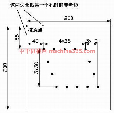
图1 黑点表示孔的圆心位 2.1 步骤一 选择图1中的尺寸“40,55”作为“表格驱动阵列的驱动尺寸”,然后选“Done”。 2.2 步骤二 选择“Add”,进行表的添加(输入一个表名如A),接着打开一个窗口,其中已有的文字均为注释语句,最后一行为: idx d4(40.0) d3(55.0) 其中,idx表示这一列填的是序号,从1开始;d后的数字以实际操作中产生的为准,括号内数值为步骤1中所选驱动尺寸的值,可以看出该值的显示顺序与尺寸的选择顺序是对应的。 2.3 步骤三 进行表的录入,依次填入:
1 65 55
2 90 55
3 115 55
4 140 55
5 50 85
6 60 115
7 70 145
8 95 145
9 120 145
10 145 145
11 170 145
12 150 85
13 160 115 其中1~4为上部右边的4个孔,5~7为左边3个孔,8~11为下部右边4个孔,12~13为右边剩余2个孔。 2.4 步骤四 首先点击“File→Save”,并且进行保存。然后点击“File→Exit”,退出程序。之后执行“Done”即可进行阵列,如图2所示。
说明:补充资料仅用于学习参考,请勿用于其它任何用途。
参考词条
|