1) converting 3D models

三维模型转化
2) 3D model converter
三维模型转换器
1.
Visualization of virtual plant based on 3D model converter;
基于三维模型转换器的虚拟植物可视化
3) three-dimensional transformation model
三维转换模型
4) 3D visualization model
三维可视化模型
1.
It is an important development direction for mining geotechnical engineering to build perfect 3D visualization model of mining geotechnique,which provides model information for analysis and estimation of stability timely and exactly,and integrative information to help geotechnical engineers to make right judgments.
建立完善的矿山岩土工程三维可视化模型,适时、较准确地为矿山岩土工程稳定性分析与评价提供模型资料,为岩土工程师对矿山岩土工程问题的正确判断、分析提供综合信息,是矿山岩土工程发展的一个方向。
2.
The construction of the 3D visualization model and the numerical model of rock slope is critical in geotechnical,hydroelectric and hydropower projects.
基于AutoCAD平台,借助AutoLisp语言,采用滑动最小二乘法插值拟合,构建三维可视化模型,同时讨论可视化模型与数值模型的转入。
3.
The 3D visualization model of jointed rocky side slope can display the characteristics of the spatial combina-tion of structural plane of side slope and reveals the destruction mode of side slope so that it is a forward subject of gen-eral interest in the research field of geotechnical engineering.
节理岩质边坡三维可视化模型可以直观地表达边坡结构面的空间展布特征,揭示边坡的破坏模式,是岩土工程研究的前沿和热点课题。
5) three-demensional digital model
三维数字化模型
1.
Objective:To generate three-demensional digital model of attachment dental.
目的 :建立附着体义齿的三维数字化模型。
6) 3D parameterized model
三维参数化模型
1.
Aiming at the problems in automatic generating 2D drawings from 3D parameterized models,such as bad view layout,unreasonable scale,untidy dimensioning,multifarious lines,and note error,etc.
针对由三维参数化模型自动生成的工程图中视图布局较差,比例不合理,尺寸标注不整洁,线条繁杂,注释错误等缺点,根据企业给定的工程图模板及相应标准,研究了工程图模板创建与保存方法、三维模型驱动后工程图视图布局、比例、特征尺寸、焊接符号、零件序号的调整方法,以及部件图明细表的自动生成与调整方法。
2.
First builds the component and whole machine 3D parameterized models and then uses Pro/TOOLKIT and Visual C ++ to achieve the secondary development of the 3D parameterized design.
首先构建零部件和整机三维参数化模型,然后利用Pro/TOOLKIT和VisualC++实现三维参数化设计的二次开发,最后简述根据三维参数化模型生成典型零部件的工程辅助视图的机理。
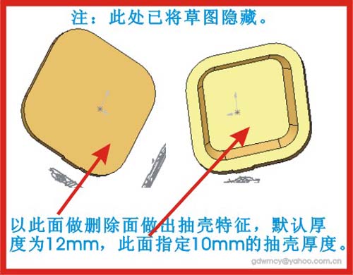
补充资料:AutoCAD二维文件转化成solidworks三维文件
图1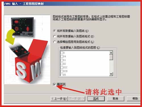
图2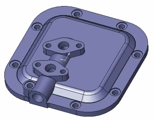
图3
图4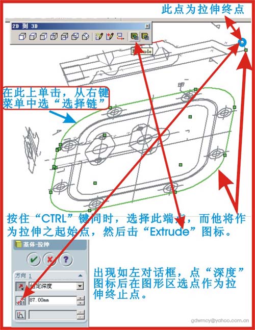
图5
图6
图7
|
说明:补充资料仅用于学习参考,请勿用于其它任何用途。
参考词条