|
|
|
说明:双击或选中下面任意单词,将显示该词的音标、读音、翻译等;选中中文或多个词,将显示翻译。
|
|
|
您的位置: 首页 -> 词典 -> 稀疏阵列<数组>
1) sparse array

稀疏阵列<数组>
2) thinned arrays
稀疏阵列
1.
Genetic algorithm and FFT for the synthesis of element weight coefficients in asymmetric thinned arrays;
运用GA和FFT确定稀疏阵列的激励幅度
2.
Genetic algorithm (GA) is used for the synthesis of thinned arrays (whose elements are thinned from the uniform grid),which uses not only element spacings but also element excitation as variables,so it provides more degree of freedom to control the characters of thinned arrays.
本文运用遗传算法 (GA)综合稀疏阵列 (单元从规则栅格中稀疏 )时 ,不仅优化单元间距 ,而且将单元激励也作为优化变量 ,从而提供了更多的自由度来控制稀疏阵列的性能 。
3) Sparse array
稀疏阵列
1.
This paper deals with the issues associated with applying space-time adaptive processing(STAP) techniques in airborne sparse array applications.
研究了机载稀疏阵列雷达杂波谱特性,提出总的孔径不变且稀疏后任意2个阵元间的间距小于等于时域脉冲的个数时,无论稀疏后有效阵元数多少,杂波协方差矩阵的秩都保持不变。
2.
In this paper interpolation technique is used for processing the FIM(Fourier Integral Method) beamforming of equispaced linear sparse array.
运用插值技术对等距稀疏阵列进行FIM(傅里叶积分法)波束形成处理,不仅有效地增加了阵元数目,而且解决了等距稀疏阵列因阵元间距大于半波长而引起的信号角度模糊问题,同时采用FIM波束形成技术提高了指向性性能和抑制相关干扰噪声性能。
4) thinned array
稀疏阵列
1.
This paper points out that a thinned array can be set with the density function of the Gaussian distribution,after the extending of covariance matrix the gain can be increased clearly.
提出利用高斯随机分布的密度函数设置稀疏阵列,稀疏阵列得到的协方差矩阵经扩展后,增益会有明显的提高。
2.
So we can use thinned array to solve these problems.
在许多工程应用中,天线阵列要求有窄的扫描波束,而不要求有相应的增益,因此可以采用稀疏阵列。
3.
On the basis of a thinned array and code division signals, the space time adaptive processing (STAP) on an airborne radar is investigated to carry out ground clutter suppression and moving target detection.
基于稀疏阵列和码分正交信号,研究了机载雷达的空时自适应处理(STAP)技术,用于空中预警背景下的地面杂波抑制和运动目标探测。
5) Sparse arrays
稀疏阵列
1.
Theoretically the aliasing of sparse arrays could be discriminated by two signals with different frequencies, but it could not be eliminated completely in the presence of noise.
理论上根据两个不同频率信号可以解稀疏阵列相位模糊,但由于噪声干扰并不能完全消除稀疏阵列相位模糊。
6) sparse COLD array
稀疏COLD阵列
补充资料:Pro/ENGINEER中复杂几何路径的数组阵列
1 引言 Pro/ENGINEER是目前应用非常广泛的CAD/CAM软件,其功能非常强大。在Pro/ENGINEER中进行特征复制时, PATTERN(数组阵列)可以一次建立多个相同的特征,比COPY(复制)省时省力。 在实际应用中,阵列的几何路径有规则的(如直线形、圆形等),也有不规则的(如平行四边形、椭圆形等)。对于规则路径,其生成较简单,如圆形路径,选取一周向驱动尺寸,输入阵列的增量与个数即可。下面以在基座上钻孔为例,介绍不规则几何路径的数组阵列。 2 设计实例 首先,生成基座(如图1黑点表示孔的圆心位),其中心点位于Pro/ENGINEER中坐标系的原点,再钻出左上角的第一个孔(以基座的两条边为参考边,这两条边的交点为准原点)。然后进行数组阵列,产生其余的孔,依次选择“Pattern→General→Table”。 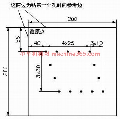
图1 黑点表示孔的圆心位 2.1 步骤一 选择图1中的尺寸“40,55”作为“表格驱动阵列的驱动尺寸”,然后选“Done”。 2.2 步骤二 选择“Add”,进行表的添加(输入一个表名如A),接着打开一个窗口,其中已有的文字均为注释语句,最后一行为: idx d4(40.0) d3(55.0) 其中,idx表示这一列填的是序号,从1开始;d后的数字以实际操作中产生的为准,括号内数值为步骤1中所选驱动尺寸的值,可以看出该值的显示顺序与尺寸的选择顺序是对应的。 2.3 步骤三 进行表的录入,依次填入:
1 65 55
2 90 55
3 115 55
4 140 55
5 50 85
6 60 115
7 70 145
8 95 145
9 120 145
10 145 145
11 170 145
12 150 85
13 160 115 其中1~4为上部右边的4个孔,5~7为左边3个孔,8~11为下部右边4个孔,12~13为右边剩余2个孔。 2.4 步骤四 首先点击“File→Save”,并且进行保存。然后点击“File→Exit”,退出程序。之后执行“Done”即可进行阵列,如图2所示。
说明:补充资料仅用于学习参考,请勿用于其它任何用途。
参考词条
|