1) inner core drawing mechanism

内抽芯机构
1.
It includes the material choice, the requirement of technology, the calculation of dimension for every formed key parts, the design and adjustment of inner core drawing mechanism for the compression mould.
介绍了冰箱门内壳吸塑模的设计 ,包括各成型关键零件的材料选择、技术要求、尺寸计算及模具内抽芯机构的设计与调
2) inner side core-drawing mechanism
内侧抽芯机构
1.
The process character of back shell bracket of mobile phone is analyzed, and both the structure and working process of injection mold of back shell bracket of mobile phone are introduced, as well as the special inner side core-drawing mechanism and slanting rejecting mechanism are stated.
分析了手机背壳支架的工艺特点,介绍了手机背壳支架注射模具的结构及工作过程,阐述了颇具特色的内侧抽芯机构及斜顶机构。
3) core pulling mechanism
抽芯机构
1.
Design of Core Pulling Mechanism of Plastics Suction Mould;
真空吸塑成型模具抽芯机构设计
2.
The mould is designed to take advantage of slanted guide pillar with core pulling mechanism and ejector in Fixed Half to solve the problem of unloading the plastic parts with raised parts in side.
该模具利用斜导柱抽芯机构及定模推出机构解决了带侧向凸起的塑件的脱模问题 ,模具结构紧凑 ,推出可靠 ,安装操作方便 ,成型塑件质量好 ,生产效率
3.
A kind of ringed core pulling mechanism of injection die of plastic casing coupling is introduced.
介绍了塑料管套注射模的环形型芯抽芯机构。
5) core-pulling mechanism
抽芯机构
1.
Research on reconfigurable design methodology of injection molding core-pulling mechanism;
注塑模抽芯机构可重构设计方法
2.
Design of injection mold with arc core-pulling mechanism
圆弧抽芯机构注塑模设计
3.
The key points in designing the side core-pulling mechanism with inclined sliding block were stated in detail.
分析了烟花尾翼塑件的结构特点,介绍了该塑件注射模的结构、工作过程及制造特点,重点阐述了斜滑块抽芯机构的设计要点。
6) core-pulling structure
抽芯机构
1.
The working characteristics of these core-pulling structures are introduced in deˉtail,and their application scopes are given.
分析了冰箱内壳零件的工艺特点,设计了几种抽芯机构,并详细介绍了这几种抽芯机构的工作特点,给出了其应用的范围。
2.
The mould design with core-pulling structure by complex vacuum forming method is mainly introduced combined with processing practice,that is how to design core-drawing structure of mould according to production structure and material characteristic,and including design plan analysis,kinetic and force analysis,some main design points.
结合生产实际 ,重点介绍了复杂真空成型模具的抽芯机构设计方法 ,即如何根据制品结构及材质特点 ,灵活设计真空成型模具的抽芯机构 ,包括抽芯机构设计方案分析、抽芯机构运动及力学分析、抽芯机构结构设计要点。
3.
The design of the core-pulling structure of the relative cylinder hinged vacuum mould was described.
介绍了冰箱内壳产品的结构特点及模具在冰箱生产中的重要作用 ,相应的气缸铰链式真空成型模具内抽芯机构的设计 ,气缸、铰链的选择计算 ,机构的工作过程 ,以及真空成型模具设计中的通用技术要求 ,双模设计中模体位置的布置 ,模具中活块与模体间隙的选择等。
补充资料:抽芯成型高差大的滑块多级锁紧结构
在压铸模设计中, 常常会遇到同一抽芯而各成型高度相差较大的零件, 如果采用斜拉杆或弯销抽芯, 习惯上采取的措施是增加滑块的高度,以满足滑块的退位空间,其结果是滑块的重量增加,模框的强度降低。
图1 是汽车油泵调速器前壳压铸件示意图, Ⅰ- Ⅰ分型面需用抽芯才能完成脱模,其最低抽芯高度Hmin 为17mm, 最大抽芯高度Hmax为45mm, 为了保证滑块有足够的退位空间而不发生自锁, 滑块的高度必须大于或等于45mm。为避免抽芯距离过大造成滑块体积增加, 在设计中采用了局部增高多级锁紧结构,如图2 所示。P 是高于17mm低于45mm的面,N是高于45mm的面,M面是与N面同高且保证N 面受力平衡的辅助结构。α为抽芯角,β1 、β2 为锁紧角,β1 、β2 不仅具有锁紧作用,而且在开模抽芯时还具有让位的作用,所以β1 、β2 必须大于α, 而且β2 应大于β1 , 否则开模时, 滑块会出现自锁。锁紧角β2 也可以等于β1 , 但由于制造时有误差, 如果误差大, 则β1和β2 形成的锁紧面会出现干涉。在压铸件调速器前壳模具设计中, α取23°, β1 取26°, β2取30°,实现了安全生产。

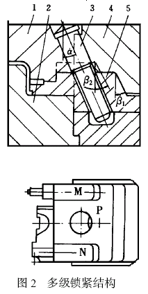
总之, 对于那些抽芯高度相差大的滑块,采用多级锁紧结构,对减小滑块的重量、延长模具寿命,节约模具材料具有重要的作用。
说明:补充资料仅用于学习参考,请勿用于其它任何用途。
参考词条