1) spatial tie arch model

拉杆拱模型
2) spatial tied-arches model
空间拉杆拱模型
3) tie-arch
拉杆拱
1.
pre-stressed deck tie-arch structure is applied to the design of Taojinhe aqueduct, which is a key structure in the Jiaodong Area Water Transfer Project of the Eastern Route of North-to-South Water Transfer Project.
淘金河渡槽是南水北调东线工程胶东地区调水工程中的一项大型关键性输水工程,渡槽采用了一种新型的渡槽结构形式——上承式预应力混凝土拉杆拱结构。
2.
A new type of structure system-top supported pre-stressed tie-arch aqueduct was used in the South-to-North Water Transfer Project.
结合南水北调工程中的某新型上承式预应力混凝土拉杆拱渡槽,运用三维有限元软件MIDAS/Gen对该渡槽的支撑结构——上承式预应力混凝土拉杆拱在各种工况下的内力分布规律进行分析,较全面地评价了其整体受力性能。
3.
A new type of structure system-top supported pre-stressed tie-arch aqueduct was used in the design of Jiehe aqueduct,which is a key structure in the Jiaodong Area Water Transfer Project of the eastern route of the North-to-South Water Transfer Project.
界河渡槽是南水北调东线工程胶东地区调水工程中一大型关键性输水工程,渡槽采用了一种新型的渡槽结构形式上承式预应力混凝土拉杆拱结构。
4) rod-arching
拉杆-拱
5) strut-and-tie model
拉压杆模型
1.
Design for reinforcement of structural concrete with Strut-and-Tie model method;
结构混凝土拉压杆模型法配筋设计
2.
Review of application and research of strut-and-tie models for concrete bridges;
拉压杆模型在混凝土梁桥中应用与研究进展
3.
Nonlinear finite element analysis of deep flexural beam strut-and-tie model
深受弯梁拉压杆模型的非线性有限元分析
6) strut-and-tie model
拉-压杆模型
1.
Reinforcement computation of strut-and-tie models for deep beams without reinforcing web;
无腹筋深梁的拉-压杆模型配筋计算
2.
Prediction of shear capacity of prestressed concrete deep flexural members based on modified strut-and-tie model;
基于改进拉-压杆模型的预应力混凝土深受弯构件受剪承载力预测
3.
Applying strut-and-tie model to concrete structure instruction;
拉-压杆模型在混凝土结构教学中的应用
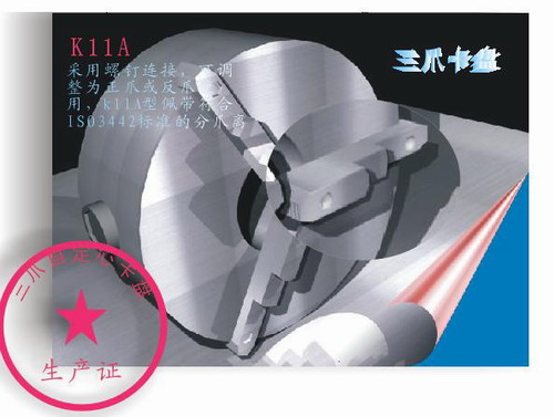
补充资料:AutoCad 教你绘制三爪卡盘模型,借用四视图来建模型
小弟写教程纯粹表达的是建模思路,供初学者参考.任何物体的建摸都需要思路,只有思路多,模型也就水到渠成.ok废话就不说了.建议使用1024X768分辨率
开始
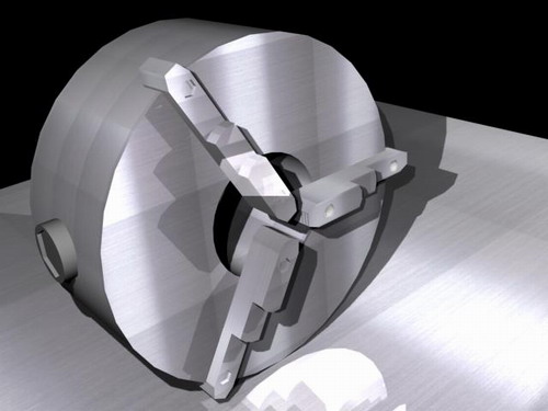
先看下最终效果
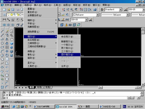
第一步,如图所示将窗口分为四个视图
第二步,依次选择每个窗口,在分别输入各自己的视图
第三步,建立ucs重新建立世界坐标体系,捕捉三点来确定各自的ucs如图

第四步,初步大致建立基本模型.可以在主视图建立两个不同的圆,在用ext拉升,在用差集运算.如图:
第五步:关键一步,在此的我思路是.先画出卡爪的基本投影,在把他进行面域,在进行拉升高度分别是10,20,30曾t形状.如图:
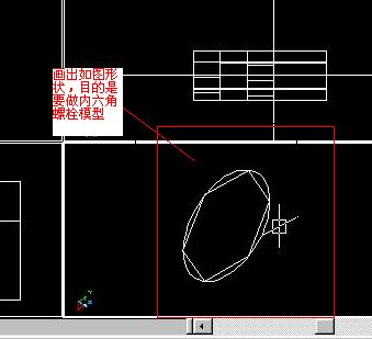
第六步:画出螺栓的初步形状.如图
第七步:利用ext拉升圆,在拉升内六边形.注意拉升六边行时方向与拉升圆的方向是相反的.
之后在利用差集运算
第八步:将所得内螺栓模型分别复制到卡爪上,在利用三个视图调到与卡爪的中心对称.效果如图红色的是螺栓,最后是差集
第九步:阵列
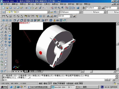
第10步.模型就完成了
来一张利用矢量处理的图片
说明:补充资料仅用于学习参考,请勿用于其它任何用途。
参考词条