1) microslip analytic model

微滑移解析模型
1.
Forced response analysis of blade system with dry friction damper using one-bar microslip analytic model;
基于微滑移解析模型的干摩擦阻尼叶片稳态响应分析
2) microslip model
微滑移模型
1.
In order to study the influence of structural parameters on the optimal normal load,a microslip model was used to formulate the nonlinear dry friction force.
为了研究阻尼结构参数对阻尼叶片最优正压力的影响,基于微滑移模型,推导出了阻尼器非线性干摩擦阻尼力的计算公式。
3) microslip discrete model
微滑移离散模型
4) slip model
滑移模型
1.
Furthermore,the gaseous flow in micro-channels are investigated numerically using continuum-based no slip model,continuum-based first-order slip model,continuum-based alternative second order slip model and molecular-based DSMC method,respectively.
对微尺度气体流动及其适用模型进行综述,并以微通道内气体流动为例,采用基于宏观连续介质假定的无滑移、一阶滑移和修正二阶滑移模型,以及基于分子运动的DSMC方法分别进行数值研究,分析不同努森数下各流动模型的适用性。
2.
The micro-channel flow is investigated theoretically and numerically at various inlet pressure ratios,aspect ratios and fluid cases with several slip models.
采用不同滑移模型,对不同进出口压比、长宽比、工质的微通道流进行理论和数值分析,着重研究稀薄效应、热蠕动效应以及不同滑移条件对计算结果的影响。
3.
The general expressions of pressure distribution,velocity distribution and mass flow rate were derived from the two-dimension(2-D) Navier-Stokes equation with general slip model equation by the perturbation expansion under isothermal assumption.
基于扰动分析理论,在等温假设条件下,由二维Navier-Stokes方程和统一滑移模型推导得到压力分布、速度分布和质量流率理论表达式。
5) Physical microcosmic analysis model
物理微观解析模型
6) analytical model
解析模型
1.
The analytical model of Maxwell magnetic suspension force of twopole bearingless motor;
无轴承二极电机麦克斯韦磁悬浮力解析模型
2.
Dynamics analytical model of 6-dof industrial robot containing closed chain;
带闭链六自由度工业机器人动力学解析模型
3.
An analytical model to predict the velocity and temperature field and heat transfer from the natural convection of an array of line heat sources in large space;
大空间单列水平线热源自然对流速度、温度场及换热的解析模型
补充资料:全面解析在AutoCAD中模型的半剖.全剖.局部剖
在cad如何做些剖切呢.今日写了一个教程,抛砖引玉,希望给大家点思路.随便做了一个模型,下面就来发张图片

图1
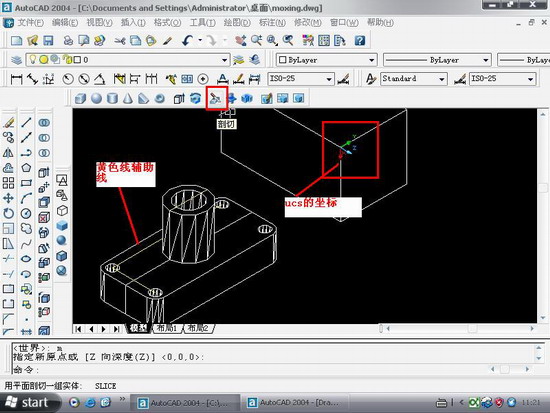
图2
用剖切面完全剖开机件所得的剖视图称为全剖视图。全剖视图用于外形简单内部结构较复杂且不对称的机件。
全剖.操作要点:xy,.XZ,YZ等平面的剖面都是依据你的ucs坐标来的,因此如果某些时候剖切得不到全剖效果的话,那就你的坐标系有问题.
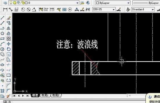
图3
最后选择b,保留两侧,得到全剖效果
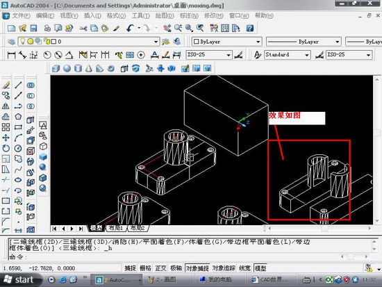
图4

图5
半剖模型:
当机件具有对称平面时,在垂直于对称平面的投影面上投射所得的图形,以对称中心线为界,一半画成剖视图,另一半画成视图,这种剖视图称为半剖视图。半剖视图适用于内外结构都需要表达且具有对称平面的机件。
画半剖视图应注意:
(1)视图和剖视的分界线应是细点画线,不能以粗实线分界。
(2)半剖视图中由于图形对称,机件的内部形状已在半个剖视图中表示清楚,所以在表达外部形状的半个视图中不画虚线,以及在后方不可见的虚线都不画。
(3)机件的形状接近于对称,且不对称部分已另有图形表达清楚时,也可以画成半剖视图。
(4)当对称机件的轮廓线与中心线重合时,不宜采用半剖视图表示。
半剖的操作与阶梯剖有点相似.只不过阶梯剖的要做多条辅助线
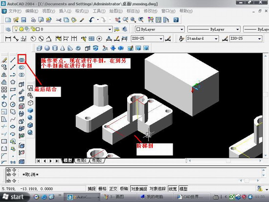
图6
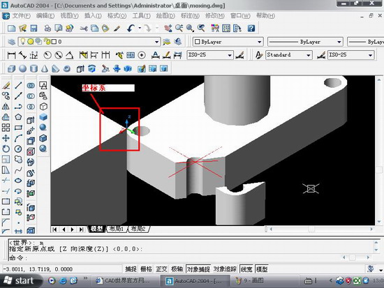
图7
局部剖:
用剖切面局部地剖开机件,以波浪线或双折线为分界线,一部分画成视图以表达外形,其余部分画成剖视图以表达内部结构,这样所得的图形称为局部剖视图。它用于内外结构都需要表达且不对称的机件。
说明:补充资料仅用于学习参考,请勿用于其它任何用途。
参考词条