1) instability monitoring component

失稳监控部件
2) snap-through monitoring
跃越失稳监控
3) monitoring and controlling of instability
失稳监测与控制
4) instability monitoring
失稳监测
1.
In order to prevent the catastrophic instabilities damage of steel structures,the methods of structural health monitoring and damage diagnostics were extended into the field of instability monitoring of steel structures,based on the relationships between structural instabilities and structural responses or their characteristic parameters.
为了预防钢结构发生灾难性失稳破坏,根据结构失稳与结构响应或特征参数之间的关系,将目前应用于结构健康监测和损伤诊断的方法扩展到钢结构失稳监测领域;评述并归纳了基于应变和位移变化趋势、基于振动-失稳相关性、基于薄壳体积改变率、基于失稳先兆的钢结构失稳监测方法;进一步对3种钢结构失稳监控部件进行了概念设计,包括钢套管压力监控、节点塌陷监控、坦拱和扁壳跃越失稳监控;总结了各种监测方法的特点和存在的问题。
5) local buckling
局部失稳
1.
The results suggest that 20% of moment redistribution at the internal support could be gained in the local buckling design of continuous composite beams with the non compact cross section(class 3).
研究了负弯矩区截面未完全塑性时出现局部失稳的连续组合梁的稳定。
2.
The analytical results show that failure of members with low slenderness ratio tends to cause local buckling,while failure of members with high slenderness ratio will cause flexural buckling.
分析结果表明:小长细比构件易发生连接肢的端部局部失稳,大长细比构件则易发生弯曲整体失稳,构件沿最小轴和平行轴失稳宜采用不同的换算长细比公式;所得结果为今后的铁塔设计工作提供了理论依据。
3.
The results show that the failure mode of extended endplate connection is the large deformation of bending taking place initially in the tensile zone of endplate and column flange,and then the local buckling of compressive zone in connection causes the loss of carrying load.
结果表明:火灾下节点的破坏模式为:首先在端板和柱翼缘承拉区发生弯曲大变形,之后承压部分局部失稳并最终导致节点丧失承载力;承压加劲肋厚度对节点耐火性能有较大影响,火灾下加劲肋受到不断加大的热应力作用,但其临界应力随材料刚度退化而不断降低,较薄的承压加劲肋易发生失稳并引发柱腹板局部屈曲导致节点失效。
6) instability position
失稳部位
1.
The failure zone caused by seismic force mainly distributed on the upside of the slope,the instability position is from 0.
通过134条实测剖面分析,研究了地震失稳斜坡坡度和失稳部位。
补充资料:将UG里的一个装配部件输出成单个部件文件
法一:
- 关闭(turn off)FileàOptions->Load Options下"Partial Loading "选项
- 打开装配部件
- 选择File->Export->Part
- 在"Part Specification"下选择"new"
- 选择"Specify Part",指定输出部件文件名称及位置
- 将"Object Selection Scope"设定为"All Objects"
- 选择"Class Selection->Select All"高亮所有对象
- 按"OK"
该种方法特点:每一个部件的特征都会汇集在新部件的MNT里。可以方便编辑。
法二:
- 闭(turn off)File->Options->Load Options下"Partial Loading "选项
- 打开装配部件
- Application->Assembly
- Assemblies->Components->Create New,给出想要输出的部件文件名及路径。
- 如下图1,在ANT上双击新产生的部件文件,使其成为工作部件。
- Assemblies->WAVE Geometry Linker,将设置改为"Body",选择所有组件的体。
- 将"Create Non-associative"开关设为"On",见下图2
- 将产生的部件设成显示部件,仅保存刚产生的新部件,不保存旧的装配部件。
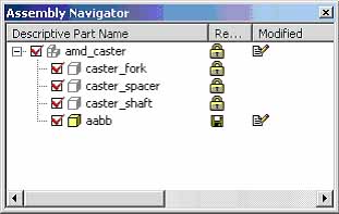 图1 | 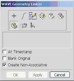 图2 |
该种方法特点:每一个部件在新部件的MNT里只会显示一个link的特征。没有相应特征可以编辑。
说明:补充资料仅用于学习参考,请勿用于其它任何用途。
参考词条